What is the L293D integrated circuit
The L293D integrated circuit is a 4-channel controller capable of handling currents in both directions of up to 600 mA in a wide voltage range from 4.5 V to 36 V. It is specially designed to control relays, solenoids, DC motors, among others. .
Its compact dimensions and affordable cost make it a convenient choice to integrate into projects with Arduino and other development boards, offering an efficient and economical solution for the precise control of motors and similar devices.
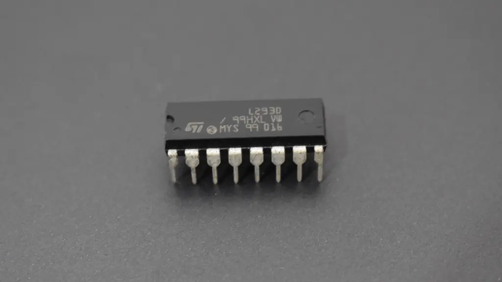
The L293D is encapsulated in a format known as DIP (Dual Inline Package), characterized by its rectangular configuration that has pins on both sides of the device.
How to identify the pins of the L293D
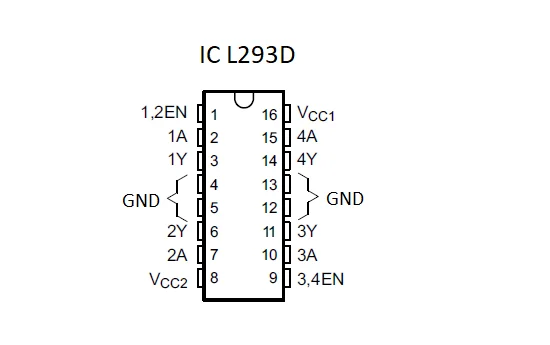
The correct identification of the pins of the L293D integrated circuit is crucial for its proper functioning. The first step is to locate the notch located at one of its ends. Pin 1 is the one located on the left. From this pin, the numbering progresses counterclockwise.
What are the functions of the L293D pins?
Enable Pins:
1.2EN: Activates controller channels 1 and 2 (left side) when PIN is set to HIGH.
3.4EN: Enables controller channels 3 and 4 (right side) by setting the PIN to HIGH state.
Controller inputs:
1A, 2A, 3A, 4A: They correspond to the controller inputs, used to receive control signals from the Arduino.
Controller outputs:
1Y, 2Y, 3Y, 4Y: These are the controller outputs to the motor terminals.
Power and Ground Pins:
GND: Connection to ground and heat sink.
VCC1: 5V supply for internal logic.
VCC2: Power supply for the motors, range from 4.5 V to 36 V.
Materials needed to control 2 motors with Arduino
For this project we will need the following materials:
1 Arduino Nano (or Arduino Uno)
1 L293D integrated circuit
2 DC motors from 3 to 6 V
1 breadboard
4 1.5 V batteries.
Jumpers
Physical connections between the L293D, Arduino and the motor
Place the L293D IC on a breadboard. Connect pin 1 (1,2EN) to pin 10 of the Arduino, then link pin 2 (1A) to pin 3 of the Arduino. Route pin 3 (1Y) to one of the terminals of one of the motors and connect pins 4 and 5 to the ground (-) rail of the breadboard. Link pin 6 (2Y) to the other terminal of the motor and link pin 7 (2A) to pin 5 of the Arduino. Connect pin 8 (Vcc2) to the positive pole of a 6V power supply.
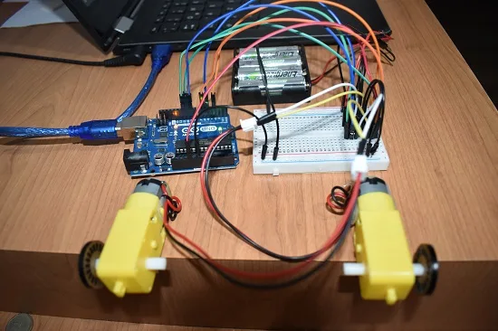
Subsequently, connect pin 9 (3.4EN) to pin 11 of the Arduino and pin 10 (3A) to pin 9 of the Arduino. Route pin 11 (3Y) to one of the other motor’s terminals and connect pins 12 and 13 to the breadboard’s ground rail. Link pin 14 (4Y) to the other terminal of the motor and link pin 15 (4A) to pin 6 of the Arduino. Connect pin 16 (Vcc1) to pin 5V of Arduino.
How to control the rotation of both motors at the same time
The connections made assign pins 3 and 5 of the Arduino to control the rotation of the left motor, while pins 6 and 9 are in charge of the right motor. By manipulating the state of the pins between LOW and HIGH, you can achieve rotation in the same direction, in the opposite direction or keep one running while the other stops.
This level of control will be critical for our upcoming autonomous vehicle project, where wheel manipulation plays a crucial role in steering management.
Code to rotate both motors forward
int leftA=3;
int leftB=5;
int rightA=6;
int rightB=9;
int enable12=10;
int enable34=11;
void setup() {
pinMode(leftA, OUTPUT);
pinMode(leftB, OUTPUT);
pinMode(rightA, OUTPUT);
pinMode(rightB, OUTPUT);
pinMode(enable12,OUTPUT);
pinMode(enable34,OUTPUT);
digitalWrite(leftA, LOW);
digitalWrite(leftB, LOW);
digitalWrite(rightA, LOW);
digitalWrite(rightB, LOW);
digitalWrite(enable12,HIGH);
digitalWrite(enable34,HIGH);
}
void loop() {
digitalWrite(leftA,LOW);
digitalWrite(leftB,HIGH);
digitalWrite(rightA,HIGH);
digitalWrite(rightB,LOW);}