
The line follower sensor (KY-033) is a component widely used in autonomous robot projects designed for line following. This versatile sensor integrates seamlessly into popular development boards such as Arduino and Raspberry Pi, making it easy for robotics and automation enthusiasts to create accurate and efficient line following systems.
The connection of the sensor to the microcontroller is done using pins or cables. Subsequently, it is programmed to interpret its signals and control the movement of the robot according to the sensor readings. Thanks to its ability to detect variations in the reflection of infrared light, the KY-033 becomes an essential resource to direct the movement of the robot in relation to the lines drawn on the ground, being especially valuable in robotics and competitions. educational projects.
How does an infrared line follower sensor work?
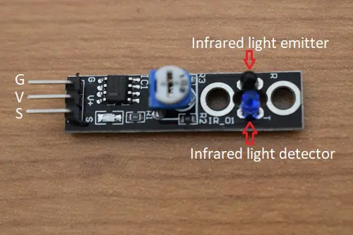
The KY-033 sensor is composed of an infrared light emitter (infrared LED) and an infrared light receiver (phototransistor). When the sensor is placed on a black line, the surface absorbs more infrared light, reducing the amount of reflected light reaching the phototransistor.
In contrast, when placed on a white surface, which reflects more infrared light, the phototransistor receives a greater amount of reflected light. These differences in the intensity of the infrared light allow the position of the sensor to be determined with respect to the line, enabling precise control of the robot’s movement so that it follows the line effectively.
KY-033 IR Sensor Technical Specifications
Regarding its technical specifications, the KY-033 operates with a voltage of 3.3 to 5 volts direct current (V/DC) and consumes between 18 and 30 mA of current. This sensor is capable of detecting objects at distances ranging from 1 millimeter to 2.5 centimeters. In addition, it has compact dimensions with a width of 11 mm and a length of 42 mm, and its printed circuit board (PCB) has a thickness of 1.5 mm.
How to connect KY-033 IR sensor to Arduino
The connection of the KY-033 sensor to an Arduino is achieved through three terminals: G (ground), V (voltage), and S (Signal). The G terminal connects to the GND (ground) pin of the Arduino, the V terminal to the 5V (voltage) pin of the Arduino, and the S terminal connects to one of the Arduino’s digital pins, such as pin 9. This configuration ensures proper electrical connection so that the Arduino can receive and process the signals from the KY-033 infrared sensor efficiently.
Code to test the sensor with an Arduino
int sensor=7;
int sensorValor;
void setup() {
Serial.begin(9600);
pinMode(sensor,INPUT);
}
void loop() {
sensorValor=digitalRead(sensor);
Serial.println(sensorValor);
delay(200);
}